Manual for MIDI Forte
The MIDI controller MIDI Forte works in three modes: regular mode, global settings and layer of register settings.
1. Global settings
After purchasing this MIDI controller it is recommended to first configure it globally and thus make it adjusted to a particular gear you are using.
Hold the Edit button for about 5 seconds. The display will show GLOB and registers will flash orange. Release the Edit button. You are in the global settings mode now, and you can edit the global parameters. Their name is written on the character display.
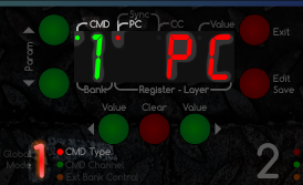 According to the global parameter which is being edited, the corresponding register shines red, or green, or orange. In addition, green parameter number will show up on the display (1 - 8 = commands, A - B = expression pedals, Π = mute, n = number, 1 = mute on, 0 = mute off) and its value will show up red (---, number, PC, CC, SYN, PGM, STO, UP, DN). There is also CMD LED dot active on the display (because the green number is the number of command this time, not the number of bank) and according to the type of edited parameter, red LED dot PC, CC, Sync or Value will light up on the display accordingly.
The following table shows all the global settings. Although at first glance it looks complicated, you do not have to use all the possibilities that the controller offers. Many users use one or two commands, others are turned off globally. Likewise, you can use eg. only one expression pedal and the second can be permanently turned off.
Abbreviation legend: PC - Program Change, CC - Control Change, SYN - synchronization commands, --- - disabled command
| Parameter name | Parameter description | Possible values |
|---|---|---|
| CMD 1 Type | MIDI command 1 | PC / CC / SYN. Command 1 can’t be turned off, it must be either PC or CC or SYN. |
| CMD 1 Channel | Command 1 channel number |
1 - 16 |
| CMD 2 Type | MIDI command 2 | --- / PC / CC / SYN |
| CMD 2 Channel | Command 2 channel number |
1 - 16 |
| CMD 3 Type | MIDI command 3 | --- / PC / CC / SYN |
| CMD 3 Channel | Command 3 channel number |
1 - 16 |
| CMD 4 Type | MIDI command 4 | --- / PC / CC / SYN |
| CMD 4 Channel | Command 4 channel number |
1 - 16 |
| CMD 5 Type | MIDI command 5 | --- / PC / CC / SYN |
| CMD 5 Channel | Command 5 channel number |
1 - 16 |
| CMD 6 Type | MIDI command 6 | --- / PC / CC / SYN |
| CMD 6 Channel | Command 6 channel number |
1 - 16 |
| CMD 7 Type | MIDI command 7 | --- / PC / CC / SYN |
| CMD 7 Channel | Command 7 channel number |
1 - 16 |
| CMD 8 Type | MIDI command 8 | --- / PC / CC / SYN |
| CMD 8 Channel | Command 8 channel number |
1 - 16 |
| CMD A Type | Expression pedal A MIDI command |
--- / CC |
| CMD A Channel | Expression pedal A default channel number |
1 - 16 |
| CMD B Type | Expression pedal B MIDI command |
--- / CC |
| CMD B Channel | Expression pedal B default channel number |
1 - 16 |
| CMD Mute Type | MIDI command CC Mute |
--- / CC |
| CMD Mute Channel | CC Mute command channel number | 1 - 16 |
| CC Mute Number | Controller number for Mute function | 0 - 127 |
| CC Mute Value On | Controller number for turning on Mute | 0 - 127; for usual setings leave on default value 127 |
| CC Mute Value Off | Controller number for turning off Mute | 0 - 127; for usual setings leave on default value 0 |
| PC Range | Value displayed in Program Change command on the display | 127: in technical format (0-127) or 128: in user format (1-128) This is the number that is showing up on the display according to how it is displayed on the receiving device (e.g. guitar effect); it doesn’t affect functionality of Program Change command |
| Calib Exp A | Expression pedal A range calibration | Value of the pedal range is showing up on the display in percentage (0 – 100). Further description bellow |
| Calib Exp B | Expression pedal B range calibration | |
| Communication mode |
Bidirectional communication with KPA or G-Major |
UNI: unidirectional communication - the controller doesn't accept any controlling data on MIDI IN and all is immediately passed to MIDI OUT BID: bidirectional communication with Kemper Profiling Amplifier or G-Major - the controller doesn't pass data from MIDI IN to MIDI OUT and in MUTE mode displays results from KPA |
| External Control Channel |
channel number for external control of banks and registers via MIDI |
EC--: external control is disabled, MIDI Forte doesn't respond on incoming PC or CC commands. EC 1 - EC16: channel number for registers control. By setting up of this channel number is enabled the possibility for external control of MIDI Forte from another MIDI controller or a computer. See chapter 4.1 Controlling the registers and banks using PC command. |
| External Bank CC Control |
CC number for external bank number switching |
B---: bank switching using CC is disabled B 0 - B127: CC number for bank switching See chapter 4.2 Switching the banks using CC command. |
| External CC Registers Low Byte |
CC number for external control of registers - low byte |
L---: controlling the status of registers 1 to 7 using CC is disabled L 0 - L127: CC number for controlling the status of registers 1 to 7 See chapter 4.3 Switching the registers using CC command. |
| External CC Registers High Byte |
CC number for external control of registers - high byte |
H---: controlling the status of registers 8 to 14 using CC is disabled H 0 - H127: CC number for controlling the status of registers 7 to 14 The same, but for registers 8 to 14, if your model has them. |
| Registers mode | Mode of individual footswitches - registers |
You can globally set each register to either the Program or Stombox mode. Just edited register number is flashing orange. PGM: Program (normal) mode - only the last pressed register lights. When one Program register is pressed, the other registers in Program mode light off. It is thus expressed switching on a specific program (effect number). STO: Stompbox mode - Stompbox registers still light either red or green. By pressing the Stompbox register, green / red color is alternating. The color thus expresses turn on/off the effect (stompbox). DN: Down mode - decrements value UP: Up mode - increments value This is overall setting of the registers for your gear. The particular decrement or increment of the values depends on settings of the register (see Chapter 3). For example, using the registers in DN and UP mode, a PC command can be sent in range from 1 to 10. But the particular type of command(s) and the range is set by editing the registers, not here in global settings. To set the mode of individual registers, you do not have to go through the entire global menu to the end. Just press the register footswitch that you want to be set. |
Table 1: Global parameter settings
It’s important to think wisely about the order of those commands, because the commands are submitted in the same order that they were set, i.e. first goes command 1, then command 2, etc. up to command 8. Of course, only if they are globally enabled. On the other hand, expression pedals won’t have any effect on order of those commands, because they are submitted only if there is a change (whenever you change the position of the pedal, potentiometer resistance will change). CC Mute only sends command if corresponding footswitch is pushed (see below).
The buttons around the display have the function indicated by white description:
- ←Parameter, Parameter→: switch between each edited parameter, ie. movement in menu
- Exit: exit from global settings mode - change to regular mode without saving, although the just adjusted global values remain in memory until you power off the device.
- Clear: reset (0) parameter value, set default value or overall disabling the command (---). When the command is disabled, it’s not possible to work with it in edit mode of a layer.
- ←Value, Value→: change parameter value
- Save: press the button for saving the values. SAVE will show up on the display. After releasing the button, the controller will go to regular mode.
1.1 Expression pedals calibration
In global settings menu, choose Calib Exp A or Calib Exp B. Register 4 LED (showing the position in the menu) will light up red in case of pedal A calibration, and green in case of pedal B calibration. The display will show the pedal name (A or B) and its current value in percentages, e.g.: “A 50” means you are calibrating pedal A and its position is on 50% of its range.
Now move the pedal to the minimum position and press ←Value button. Then set the pedal to the maximum position and press the Value→ button. This defines the minimum and maximum range of the connected pedal. For permanent save push the button Save, same as it aplies to all other global parameters.
After the calibration is carried out, the controller will calculate correct position of the pedals on the entire range of MIDI controllers from 0 to 127. Without the calibration, the pedal would have limited range and values would be e.g. from 2 to 120.
By pressing the Clear button, default values will be set, i.e. for full range, without calibration.
1.2 Exiting the global settings
When you press the Save button, the display will show SAVE and global settings are stored in premanent memory. When you press the Exit button, the global mode terminates, the settings will work, but it will not be stored permanently. This means that after switching the controller off and on, only a global setting that was stored by the Save button, starts up.
2. Regular mode
After you turn on the controller or exit the global settings, the controller is ready for controlling MIDI devices. Display shows green number of bank and red number of register - number of layer: 11-1.
2.1 Change of register and layer
After pressing the register footswitch (1 to [3 to 7 or A to C] - depending on the model of the controller), the controller will switch to the first (red) layer of the register. It will send MIDI commands that are programmed for this layer of this register in this bank. Another push of the footswitch for the same register will switch you to the second (green) layer of the register and MIDI commands programmed for this layer of this register in this bank are sent. Pressing the same button again will get you to the first (red) layer, then to green layer etc.
2.1.1 Program, Stompbox and Down/Up mode
To better understand this feature, you can imagine that you have a model 10F1D, which has 10 footswitches, of which two are for selecting the bank and the remaining 8 footswitches are for registers 1 to 6, A and B. (For term register, also the common word preset could be used, but it is not entirely apt, because with the concept of two layers, each register has two presets.) Then imagine that registers 1-3 you have configured globally to the Program mode, registers 4-6 you have globally configured to Stompbox mode, register A to Down mode and register B to Up mode. So you will use the registers 1-3 to select the program number in guitar multi-effect and registers 4-6 to turn on and off individual effects of the program (eg. on / off the delay, gain or equalizer for solo). You can use the register A for decrementing and register B for incrementing the program number of your vocaliser.
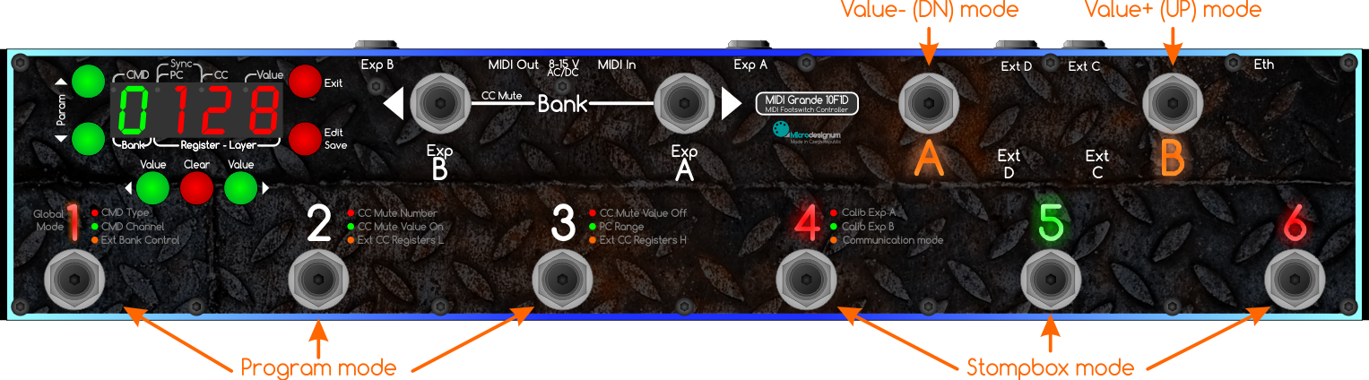
Figure: Example of global configuration of Program and Stompbox mode of registers.
For those registers that are configured globally to the Program mode (here 1-3), always only one of them lights. By selecting a particular register (eg. 1) all other program registers (2-3) turn off and only one elected register remains on (1).
If some registers are configured to Stompbox mode (here 4-6) at the beginning all stompbox registers light red. The choice of a particular stompbox register will switch the register to green and respective MIDI commands are sent, while the other registers will not turn off. Another push of the register footswitch will switch the register to red and respective MIDI commands are sent. Thus it is possible to have an overview of switched on (green) and switched off (red) effects in the connected multi-effect. The status of registers is maintained even when browsing between banks. E.g.: in the first basic bank you have turned on the registers as follows: 1 2 3 4 5 6. You switch to another bank, the default status of registers is 1 2 3 4 5 6 - everything turned off. You can change it any way you want and switch back to the first bank. The status of registers of the first bank is again as before switching to another bank: 1 2 3 4 5 6. The display shows the number of last selected register (just as in the Program mode). This information is not so essential in Stompbox mode, however, it is important when editing - to let you know which register and which layer you will be editing when you press the Edit button (this will be discussed later).
The registers A and B are globally set to Down mode (value decrement) and Up mode (value increment). They permanently light orange and their pressing doesn't affect any other registers. When any of them is pressed, the display shortly shows the value that is being sent to MIDI output. In fact, by configuring two registers to Down and Up mode, we get the function of miniature MIDI controller MIDI Piccolo 2F1D. Moreover, it is possible to set to Down/Up mode to more register pairs and control another device or parameter by each register pair. For example, decrease/increase the program number of a vocaliser and the volume of a guitar multieffect. How to set it up specifically, can be found in the chapter on layer editing below.
2.2 Bank change
Pressing the button ←Bank or Bank→ will change the bank number. By default, no MIDI commands are sent on changing the bank. The response after the bank change is different depending on that in which mode is last pressed register:
- In Program mode, the current active register will start flashing and the controller will wait for selection of register. After pressing a register button, commands to first (red) layer of corresponding register will be sent.
- In Stompbox mode, the combination of red/green registers is lit immediately for the selected bank.
Bank number is showing up green on the display: 1 - 9 and A - Z (without the letters that are not displayable on the 7-segment display), that means 32 banks total.
If you globally set sending Control Change (CC) commands on footswitches <Bank and Bank>, then on pressing the Bank footswitch, CC with value 127 is sent, after release the footswitch, CC with value 0 is sent. MIDI channel number is that which is globally set for CC Mute command.
2.2.1 Banks and slots browsing in Kemper Profiling Amplifier
See the topic Banks and slots browsing in Kemper Profiling Amplifier on MIDI Forte forum.
2.3 Mute
After pressing and holding the footswitch ←Bank, the Mute mode is activated, which sends a MIDI command Control Change CC Mute On into receiving device, with the parameters specified in the global settings. The controller now does not respond to pressing register footswitches.
If you have properly set the number and value of CC Mute in accordance with your multi-effect specification, then the multi-effect responds to this command by switching to MUTE mode, that does not pass the guitar signal to the output. Some multi-effects start to show the tuner (eg. Digitech GSP1101). Other ones display tuner while the tuner results are also sent to the MIDI output for further processing (eg. Kemper, G-Major).
The Mute function will stop by another pushing of ←Bank footswitch. It will send globally set MIDI command Control Change CC Mute Off with value, which can be different from activation of Mute On function. This will return the MIDI controller to regular mode.
It is possible to turn of Mute function globally.
2.3.1 Tuner visualisation in Mute mode
Currently, MIDI Forte in Mute mode can display the tuning results from the Kemper Profiling Amplifier (KPA), TC Electronic G-Major and Fractal Audio Axe-FX. The video of the tuner, which MIDI Forte displays, is presented on the MIDI Forte main page.
See also: Setting up the communication with TC Electronic G-Major on MIDI Forte forum.
If there were any other multi-effect, which could send the results of a tuner over MIDI, we will be happy if you inform us about it. According to our findings, only these three worldwide send the tuner results via MIDI for processing in a MIDI controller.
2.4 Expression pedals
Expression pedals are not a part of this MIDI controller. However, the controller allows you to connect the pedal, evaluate the resistance of the potentiometer and translate this value into MIDI command. It works with any passive pedal with potentiometer and standard 6.3 mm stereo TRS jack: there is power supply on tip, potentiometer slider on middle ring and ground on sleeve.
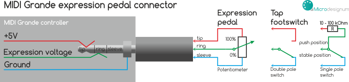
Figure: Schema of connector for expression pedals in MIDI Forte. If the connector isn't used for expression pedal, it can be used for external footswitch, for example for Tap tempo.
If you have an expression pedal enabled globally and also you have it turned on in the active layer, inscription Exp A, respectively Exp B (near the bank footswitches) light by continuously changing color from blue to red depending on the current position of the pedal. When the pedal is at 0, inscription lights up blue. When the pedal is at a value of 127, inscription lights up red. When the pedal is somewhere between extreme positions, the inscription lights by the appropriate ratio of blue and red colors. This gives you an instant overview of the pedal position, without having to move it. When the inscription Exp A, respectively Exp B lights, it indicates that it is turned on in the active layer.
When you change the position of the pedal, at the same time on the screen briefly displays the value that is being sent to the MIDI output, eg. A123. After one second, the information on the display returns to display numbers of bank-register-layer, eg. 84-1.
If an expression pedal in the active layer is off, the MIDI controller does not respond to its movement, does not send anything to the MIDI output, its inscription doesn't light, nor is it displayed its value on the display.
MIDI Forte has two "sublayers" of expression pedal in each layer. They are toggled by pressing a toe switch if a pedal has it. The first sublayer blinks red and it is default. If the toe switch is pressed, the blue sublayer is activated and another CC on selected MIDI channel can be sent by the same expression pedal. If the toe switch is pressed again, default red sublayer is activated again. But a special pedal is necessary (we offer them too).
3. Edit layer parameters
For setting up MIDI commands which are supposed to be sent while choosing the register, you first need to choose bank, register and layer. E.g.: you want to edit red layer of second register in 8th bank. The display shows: 82-1. Shortly press and release Edit button. EDIT will shortly show up on the display. This will get you to editing mode for selected layer and register of selected bank. You can edit those commands which are turned on in global settings. I.e. when a command is globally turned off, it isn’t possible to edit it and it will be automatically skipped. E.g.: if command 2 is globally turned off, after editing command 1 follows command 3. Display shows parameter number in green (1 - 8 = commands, A - B = expression pedals) and its value in red. There is also CMD LED dot active on the display (because green number is the number of command this time, not the number of bank) and according to the type of edited parameter, LED dot PC, CC or CC + Value is active.
MIDI command Program Change has only one parameter - program number, while Control Change has two parameters: number of controller and its value. That’s why CC command has a Value parameter moreover compared to PC.
Button functionality is similar to global settings. Buttons have their function marked with white text:
- ←Parameter, Parameter→: switch between edited parameters.
- Exit: quit the editing mode, switch to regular mode without saving. Set parameters will remain in memory until you switch to different layer or different register.
- Clear: reset (0) parameter value or overall disabling (---) the command in edited layer. Even if a command is globally enabled, you don’t have to use it in this particular layer and you can disable it; then it does not not apply and is not sent to the MIDI output.
Example: You have globally enabled commands no. 1 and 2. Command no. 1 is globally configured asProgram Changeon channel 1 and command no. 2 is globally configured asControl Changeon channel 1. In the edited layer you want to setProgram Change 10. Therefore set Command 1 to value 10, then press Parameter→, it will take you to the editing of the second command, and press Clear. By this the second in command will be off, and in this layer it does not apply. - ←Value, Value→: change parameter value
- Save: hold the button for saving the values. SAVE will show up on display. After you release the button, the controller will switch to regular mode.
3.1 Setting the range of expression pedals
In editation of each layer, any number of Control Change can be assigned to both expression pedals and also it is possible to define a range of values that are to be sent. E.g. if you want to set the expression pedal A to Control Change no. 7 (which is normally used for Volume) with a range from 50 to 100, go using Parameter→ button in editation of the layer to the expression pedal A setting. Set A 7, then press again Parameter→ button. The display will flash briefly abbreviation MIN: AMIN and displays the minimum value of the range: A 0. Using the Value→ button set A 50. Press again Parameter→. The display will flash briefly abbreviation MAX: AMAX and displays the maximum value range: A127. Use the ←Value button to set A100.
The same principle applies to the expression pedal B.
You can also set the opposite direction of movement of the pedal, for example from 100 to 50.
3.2 Setting the name of the preset
Press the Parameter→ button until the segment display shows NAME. A cursor on the character display blinks on the first position.
- Clear button changes the group of the edited character: A / a / 1 / space (special characters)
- ←Parameter, Parameter→ buttons move the cursor right or left
- ←Value, Value→ buttons change the edited character
3.3 Save and Save As
When you have finished the setting of the layer, briefly press the Save button. It will save the setting to permanent memory.
If you want to save the settings to another layer, another register, or to another bank, press and hold the Save button for a while. The display will blink SvAs (Save As). Select the bank, register and the layer where you want to save the settings. Then press Save. This will permanently store the settings to the newly selected layer.
4. External control
MIDI Forte controller can act as a MIDI-controlled MIDI controller, or as a bank of MIDI messages. By receiving one MIDI command, it's possible to send up to 8 MIDI messages that are programmed by the user and stored in the permanent memory of MIDI Forte. If you don't intend to use this feature, you can skip thi chapter.
4.1 Controlling the registers and banks using PC command
When the channel number EC 1 to EC16 is globally set, the ablility of MIDI Forte to be externally controlled from another MIDI controller or a computer is enabled.
When MIDI Forte receives the PC (Program Change) command on this channel, the appropriate register is activated in appropriate bank. For example, with 6F1D model, which has 4 registers:
- PC#1 activates register 1 in bank 1
- PC#4 activates register 4 in bank 1
- PC#5 activates register 1 in bank 2
- PC#8 activates register 4 in bank 2
- generally: PC#x activates:
bank ((x-1)/number of registers of controller)+1;
registrr (remainder+1)
There is nothing complicated about it, the register and bank numbers are simply in succession. When counting the register number, skip to the next bank and count on.
After receiving the command, the red layer of the addressed register is activated, so it lights up red, and simultaneously MIDI messages are sent that are before programmed by the user for this layer.
If the same PC number is received twice, the green layer is activated, just as if the register was pressed with the footswitch.
When this external control function using PC command is enabled, the controller doesn't resend the incoming PC message, because the incoming PC message is handled as a control message only for MIDI Forte in this case. If you want to resend the same message, program it on the first (or any other) command of each layer.
4.2 Switching the banks using CC command
By setting the global CC for external banks switching (Ext Bank Control), the option for controlling the banks by CC is enabled. When this CC is received, the bank corresponding to this CC value is activated. For example, let's set CC#16 for banks switching in the global configuration. When <CC#16, value=9> is received, MIDI Forte switches to the bank 9.
When this bank switch is carried out, nothing is sent to MIDI output. Only the status of the registers in stompbox mode is set.
4.3 Switching the registers using CC command
By the global setting of the CC for extern registers switching (Ext CC Registers L a Ext CC Registers H) an option for external controlling of the status of the registers is enabled. The status of the registers is set as a bit mask. For example, let's set CC#17 for Ext CC Registers L and CC#18 for Ext CC Registers H. If we would like to switch the stompbox-mode registers 1 and 6, it corresponds to the bit mask 0100001 (read from the back - one is on the first and the sixth position). It is number 0x21 hexadecimally or 33 decimally. Let's send command <CC#17, value=33> from an external MIDI controller. The registers 1 and 6 are activated to the green layer, others stay in red layer. When we send <CC#18, value=01> from an external MIDI controller or a caomputer, register 7 is activated to the green layer, others stay in red. (If your MIDI Forte model doesn't have so many registers, it doesn't respond on the bit addressing of the non-existing registers.)
It is also possible to activate even the registers in program mode. They are always set to the default - red layer. If we would like to accidentally activate multiple registers in program mode at a time, MIDI Forte doesn't allow it of course. It will activate only the register with the highest number (in binary expression is most left).
Unlike addressing registers with a PC command, in this case, only the registers are activated, but any user programmed MIDI messages are not sent to the MIDI output.
You can use the activation of the banks and registers in that case when you, for example, during a live performance activate the appropriate bank, registers and stompboxes before every song from a computer. Then, when a song is played, you control your gear using the footswitches. It is a simple way for you to prepare the controller for a particular song using a small number of MIDI commands sent from your computer while setting up the whole gear.
5. Global reset
If you wish to reset controller settings and restore default (factory) settings, turn off the controller, bring your girlfriend to help you and simultaneously push all three red buttons Clear, Exit and Edit, while you let other buttons unpushed and turn on the controller. This will set the default global values and erase settings for all layers. Display will show how many kilobytes of memory has been erased already + RES abbreviation (stands for Reset), e.g.: 4RES.
Global memory deletion takes about 10 seconds. The controller will then be reset to those values as it come to you from the factory, which in various versions may differ slightly.
6. Examples of configuration
- For examples, tutorials and detailed explanations of configuration, please visit our MIDI Forte forum.
- We recommend especially a video tutorial How to configure MIDI Grande for controlling Kemper Profiling Amplifier.
We wish you creative and fun times with this MIDI controller!